
Boom lift series

Self-Propelled Articulating Boom Lifts

Trace the chassis route from access gate to work position.

Define the work point, horizontal obstacle, platform task, equipment position, movement route and site conditions before requesting a configuration review.

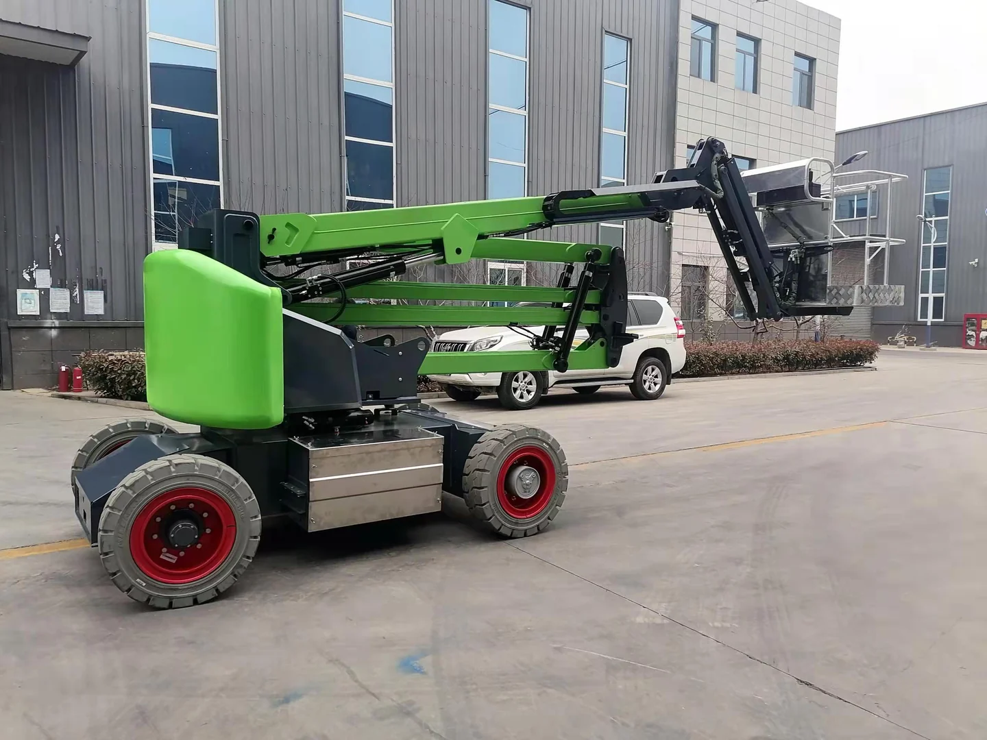
Complete green self-propelled articulating boom lift folded outside a building
Folded position · complete equipment view

01 / Category boundary

Define the task before the configuration.

A self-propelled articulating boom lift combines an articulated platform boom with an integrated powered travel chassis.

The series name identifies the carrier and boom path shown here. It does not confirm a model, working envelope, platform capacity, transport condition, power option or application suitability.

This product line is handled as a custom configuration; project requirements are collected before quotation.

Work point
Locate the platform task relative to the equipment setup position.
Obstacle geometry
Measure the height, depth and horizontal offset of structures that must be crossed.
Powered chassis
Describe the required travel, steering space and work-position envelope for the integrated chassis.

02 / Equipment guide

Understand the structure and compare the task.

Connect the equipment arrangement to your work area, movement route and operating conditions.

Structure and movement

This series describes a self-propelled base and an articulating boom path. The joints organize the arm movement, while the base position provides the reference for the requested platform location. The family name does not establish a particular drive mode, power source or working envelope.

Mark the work point and its offset from the proposed base position. Describe walls, equipment and overhead obstructions between those points. Then trace movement between setup positions, including doors, turns and changes in ground conditions.

Compare the series in context

Use the boom family page to compare the self-propelled and towable positioning tasks. Develop the requested boom path and site layout on this series page. Keep any proposed control, drive or platform arrangement tied to the specific project discussion.

Conditions to establish

Provide a plan or elevation drawing with the base position, work point, horizontal offset and obstacles. Include platform activity, available setup area and power context. Photos provide useful context but cannot establish reach, ground or slope limits.

03 / Applications

Place the equipment in its working context.

Start with the task, access route and surrounding conditions, then review the configuration against the complete site brief.

01

Access around an obstacle

Describe elevated work points that require both vertical and horizontal access planning.

02

Powered-chassis movement

Review projects where an integrated travel chassis must follow a defined site route.

03

Ground-and-access coordination

Bring the surface, turns, clearances, setup position and transport route into one review.

05 / Selection inputs

Define reach, movement and setup together.

Separate measured geometry from the operating task so the boom structure and carrier can be reviewed against one clear site layout.

  1. 01

    Vertical work position

    State the platform position and actual work point separately.

  2. 02

    Horizontal offset

    Measure from the planned machine position to the nearest and furthest task points.

  3. 03

    Obstacle profile

    Show walls, roofs, machinery, openings and overhead restrictions.

  4. 04

    Powered chassis

    Describe the required travel, steering space and work-position envelope for the integrated chassis.

  5. 05

    Ground and access route

    Provide surfaces, slopes, thresholds, doors, turns, overhead limits and transport constraints.

  6. 06

    Platform and environment

    Describe people, tools, materials, ground, weather exposure and destination.

06 / Project path

Turn site information into a reviewable brief.

Keep the project sequence visible so measurements, configuration questions and supporting files reach the enquiry together.

  1. 01

    Map the work envelope request

    Record the work-point position, offset and obstacle profile without assuming a published reach.

  2. 02

    Document the chassis route

    Describe the ground, slopes, turns, edges, openings and access restrictions.

  3. 03

    Review task and transport

    Add the platform activity, environment, storage, delivery and destination information.

07 / Buyer questions

Planning FAQ

Common questions about equipment selection and preparing your enquiry.

01 What dimensions should I send?

Send the equipment setup area, work-point height, horizontal offsets, obstacle profile and the narrowest point on the movement route.

02 Can I select this series from height alone?

No. Horizontal access, carrier, setup area, platform task, ground and transport also affect the project review.

03 Why show folded and extended views?

The folded view explains the carrier and transport envelope; the extended view explains the boom structure and platform path.

04 Do these images confirm performance?

No. They show the general equipment structure and do not establish a model or working envelope.

Start the project brief

Send the interface, route and site context.

The product family is carried into the enquiry form so the follow-up starts from the right category.

Request a project review
Quick enquiry Full quote